|
Bf 109 Slats |
Over the years, all manner of explanations have been offered about the slats on the Messerschmitt 109 family, some of them fairly accurate and some of them downright ludicrous. This article should help to clarify the operation of the slats, their mounting, and their operation.
First, let's discuss what they are NOT:
- They are not motor-operated.
- The port and starboard slats are not connected to each other.
- They are not fixed in one position.
- When extended from the wing surface, they are not "dropped"- they are extended.
This slat design was first proposed by Sir Frederick Handley Page around 1919 as a way to maintain airfoil efficiency at high angles of attack. As the airfoil pivots at a greater angle from the direction of airflow, the point at which the flow detaches from the upper wing surface moves further and further forward. Eventually, if this condition continues, the airflow "unsticks" completely from the upper surface, and the wing stalls. In order to delay this action, the slat on the 109 extends outwards under aerodynamic pressure, channeling airflow back up and over the wing upper surface, thereby maintaining airfoil effectiveness. The following diagram may help illustrate the airflow characteristics mentioned above:
On the left is a wing featuring a leading edge slat and trailing edge flap. On the right, the extended slat allows airflow to travel behind it and on over the upper surface of the wing. The trailing edge flap is also deployed in the diagram to the right, thereby increasing the camber of the wing and improving lift.
A common question asked regarding the 109 is "Should the slats be in or out when the aircraft is parked?" The answer is "yes". The slats are free-moving devices, and are commonly seen extended in many wartime and contemporary photos; however, if manually pushed back into the wing, the slats would remain there until the aircraft moved, at which time they would extend of their own volition. This action was confirmed by Günther Rall when questioned by Lair visitor Erik Whipple some time back; according to Gen. Rall, it was common practice at their field to push the slats in once the aircraft were secured so that no dust or debris would accumulate in the traveling tracks. Evidently at least one new pilot was lost due to faulty operation of the slats when taking off, which led to this practice. However, as with almost everything else 109-related, if the position of the slats is of serious concern to you when building a static model, consult your references to determine the best configuration.
So, now that we've very briefly covered what they are and what they do, let's take a detailed look at the slat systems of the Bf 109. The manual illustrations below are taken from an official factory manual for the Bf 109E; however, the Friedrich retained a similar design for slat operation as the diagram below will show. It should be noted that two major differences introduced on the F version were a reduction in slat span from 2292.5mm to 1800mm, and the elimination of the inboard to outboard connecting linkage (seen below in the Emil diagrams). The basic swing-arm movement, function and operation of the slats remained the same, however.
UPDATE: I contacted Claus Colling, one of the men behind Flug Werk (the company producing new-build Fw190s and also responsible for much 109 restoration work), and specifically asked him about the swing-arm versus roller-track slat travel design. His answer appears below:
The Me (Bf ) 109 "E" through "F" used the swing arm parallelogram mechanism to agitate the slats. From the "G" onwards the Me 109's used the roller-track mechanism to guide the slats in and out. It all follows a patent bought by Messerschmitt from DeHavilland just prior to the war. The slats are driven out by means of low air-pressure if the AOA gets higher ( slow flight ) and retract by means of air-pressure when accelerating...
The most interesting thing about this is that there are clearly several significant differences between the Friedrich and Gustav wings, despite their outwardly identical appearance. The radiator ducting and the slat mechanism are both different; it will be interesting to see what further differences are evident!
|
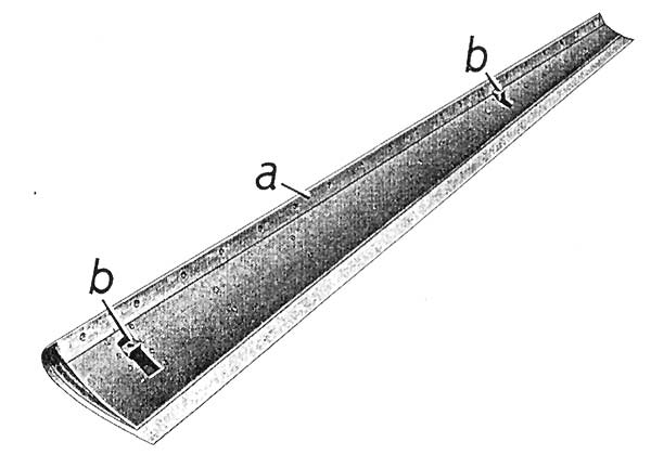
The slat itself is a rather simple affair; a single airfoil-shaped streamlined structure as shown at right.
a- wooden leading edge backing b- bearing mounts |
|
|
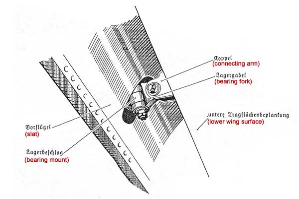
The slat mounts to the extension arms as shown in the notated diagram at right; this is applicable to inboard and outboard mounts. |
|
|
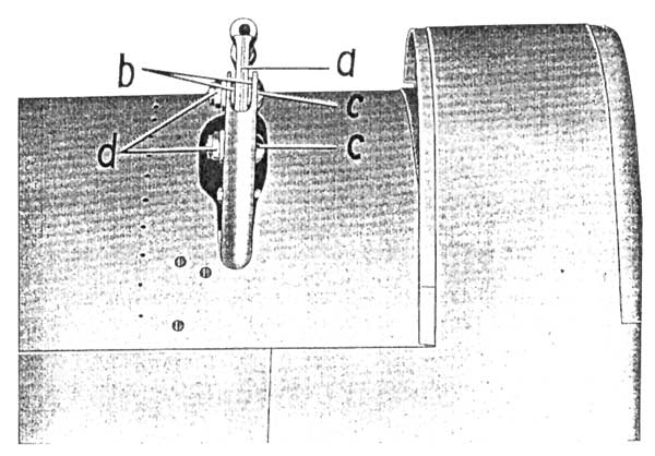
In the diagram at right, we see an overhead view of the port inboard slat arm, with the parts noted as follows: |
|
|
The connecting linkages between the inboard and outboard slat travel arms are illustrated at right:
a- Pivoting linkage b- Pivot linkage mount (to spar) c- Retaining nut d- Slat travel arm connection rod e- Connecting rod mounting fork f- Inter-slat connection rod g- Washer h- Retaining nut
|
|
|
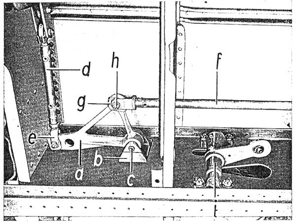
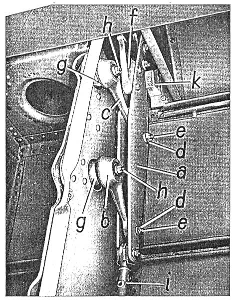
As can be seen in the photo at right, the slats made use of a complex swing-arm linkage assembly which ensured proper alignment at all times.
a- Slat pivot arm b- Rear slat arm pivot linkage c- Forward slat arm pivot linkage d- Washer e- Retaining nut f- Slat mounting fork g- Pivot linkage bearing (2) h- Pivot arm retaining nut (2) i- Mounting arm connecting rod k- Guide block |
|
|
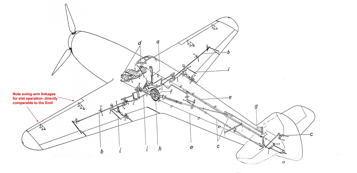
Finally, this diagram gives a good overview of the systems noted above, which should help make the overall operation of the slat much clearer.
a- Slat pivot arm assembly b- Mounting arm connector rod c- Pivoting linkage arm d- Inboard/outboard slat arm connector rod |
|
| Recent discussion on the Forum has indicated that a different, less complex arrangement utilizing a roller track was introduced at some point in production; however, as seen at right on the "Schmierplan" (lubrication point chart) for the Friedrich, the swing arm assemblies are still shown. Enquiries have been made to individuals and companies which have recent experience with 109 wing construction regarding this changeover, and this article will be updated with the results of these queries when they become available. |
|
|
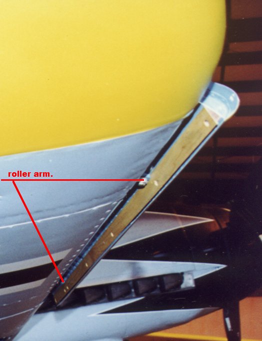
In this photo of W.Nr.610937 from Will Riepl, the wooden slat backing can be seen as well as the two castle nuts which mount the slat to the arms. |
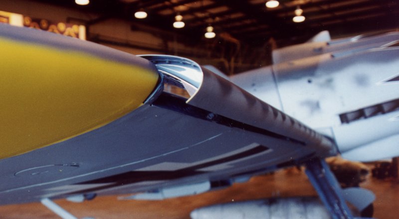
Another view of 610937's extended slat shows that the slat structure ends slightly inboard of the actual slat skinning itself. |
Hopefully this article has been of some help in understanding the function and operation of the leading edge slats on the 109.