|
As regards the
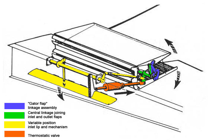
mechanical operation of the flaps themselves, the diagram at right should
help clarify a few salient details of this compact and complex
design. For an explanation of the actual function of the flaps, I'll
defer to Graeme Snadden, a member of the "Black 6" team
who maintained Bf 109G-2 W.Nr. 10639 in immaculate airworthy condition for
a number of years. He posted the following information in the forum
which is immensely helpful in understanding the relationship between the
various flap elements:
"... I have a little advice to offer. This advice is given with more than a little knowledge of '109's (having had 'Black 6' in my family so to speak, for 30 years.)
An oft seen error when positioning flaps on a '109 is the relationship between the split cooler flaps and the mid-span landing flaps.
In relation to the landing flaps (which appear to be at the 40 degree full down position), with the cooler flaps full open, the lower flap would be in line with the landing flap and the top flap would be about 10 degrees below the top surface of the wing (in line with the trailing edge of the wing fillet.) With landing flaps full down, in the automatic setting on start-up from cold, the flaps would motor shut, leaving the lower flap stationary whilst the top flap motored closed to leave a gap of about 125mm. Viewed in plan, this would mean that you would see the lower flap protruding beyond the upper. If the pilot were to then raise the flaps prior to taxiing, the cooler flaps would then come to a position where they were symmetrically positioned with the chord of the wing with little more than a 10mm gap at the trailing edge.
On the ground, due to the poor cooling capacity of the small radiators, the flaps would often motor open whilst taxiing (in fact with Black 6 we preferred to allow them to open before taxiing since the reaction time of the automatic system could be so sluggish at times that a couple of blips of the throttle would nudge the temperature up toward the 115degC limit!)
With the landing flaps fully raised, the opened cooler flaps would be symmetrically deployed about the midpoint of the wing in cross section (fore & aft) with an angle of approximately 35degrees between them.
This rather lengthy little ditty should help obtain a slightly more realistic looking '109 model. Cheers!" |