|
Identifying DB605AS vs. DB605D-engined aircraft |
Part Two:
The DB605D Family
As seen in the previous installment, the AS engine was conceived as a way to boost the high-altitude performance of the existing DB605A engine, and incorporated many features of the DB605D which was undergoing a lengthy development process. Although similar externally to the earlier A-series motors, the D had numerous internal changes, among which was a redesigned head and valve train; the A model had four valves per cylinder (two inlet, two exhaust) while the D had a single inlet valve and two exhaust valves (source: JaPo, p. 81). The other mechanical particulars of the D model engine are as follows, as given by Janda and Poruba in the KaPo book (formatted as per Janes' for commonality's sake):
|
TYPE.- Twelve-cylinder inverted Vee liquid-cooled. CYLINDERS.- Bore 154mm., Stroke 160mm., Capacity 35.8 litres. Compression ratio 8.3:1 (left block) 8.5:1 (right block). One inlet and two exhaust valves per cylinder. FUEL SYSTEM.- Bosch direct-injection pump PZ 12 HP 110/25 (9-2305 E-2) mounted between the cylinder blocks. L'Orange injectors (9-2261D) on inside of cylinder blocks. Fuel supply pump (Graetzin ZD 500E) located behind right rear cylinder bank. SUPERCHARGER.- Single-stage centrifugal type, engaged by hydraulic clutch with gearbox. Effective to 6.8 km. Intake volume regulated by two throttle-regulated valves in intake manifolds linked to injection pump, and one supercharger-mounted valve mechanically linked to the two main valves and a barometric pressure sensor. IGNITION.- Dual Bosch magnetos (ZM 12DR 16 or ZM 12CR 8) mounted at the top of the rear cover. 24 Beru F280E43 spark plugs (9-4158A) were standard equipment, but Bosch 250ET 10/1 (9-4080F-1) plugs could be used in engines with a max boost pressure of 1.8 ata. The Bosch plugs would need to be inspected after every fourth engine operation. LUBRICATION.- 50 liter tank mounted forward of engine pumped through a filter to the crankshaft bearings, reduction gear, supercharger clutch, and camshaft. Return flow scavenged from camshaft covers by suction pumps into Fo987 oil cooler. STARTER.- Bosch electro-mechanical inertia starter. AIRSCREW REDUCTION GEAR.- .594:1 PERFORMANCE.- Figures from Janes' 1945 Aero Engines book as follows: DB605DB: Take-off and emergency 1,800 h.p. at 2,800 r.p.m. at 1.8 ata at sea level, 1,530 h.p. at 2,800 r.p.m. at 1.98 ata at 19,600 ft. Climbing 1,275 h.p. at 2,600 r.p.m. at 1.3 ata at sea level, 1,150 h.p. at 2,600 r.p.m. at 1.3 ata at 25,600 ft. Maximum cruising 1,075 h.p. at 2,400 r.p.m. at 1.15 ata at sea level, 1,050 h.p. at 2,400 r.p.m. at 1.15 ata at 25,200 ft. DB605DC: Take-off and emergency 1,800 h.p. at 2,800 r.p.m. at 1.98 ata at sea level, 1,800 h.p. at 2,800 r.p.m. at 1.98 ata at 16,700 ft. |
The differences between the B and C variants of the engine have been previously discussed, and the function of the MW50 system (along with the differences between a factory installation versus that installed in the field) will be addressed in a separate article.
Having thus covered the basic differences between the AS and the D engines, we can now focus on two equipment items as being ALMOST certain identifiers of one variant or the other...
Clue #1:
The Oil Fill Hatch
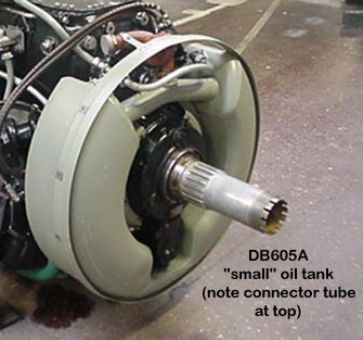
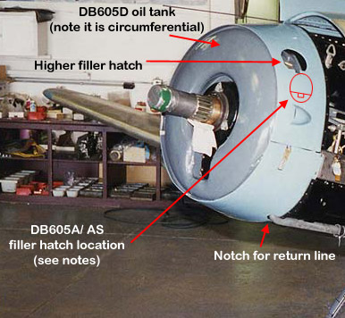
Visually, there are a few important items which are applicable only to the DB605D, and which we can use to determine whether a given airframe is a true D-engined variant, or an AS version. The first and most obvious is the larger 50-liter oil tank mounted immediately behind the spinner backplate. The DB605A family (including the AS versions) featured the standard 38.6 liter tank which is shaped like a horseshoe when viewed from the front, and which has the port filler hatch located immediately above the forward-most cooling scoop on the cowling. The larger oil tank of the D motor necessitated relocating the filler hatch upwards a few inches, and the difference is noticeable in the following photographs:
|
|
|
Of course, for every rule, there is an exception, especially with the Bf109.
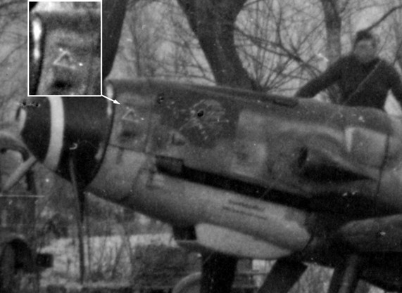
In the photo to the left, Ferdinando D'Amico shows us the nose of Magg. Bellagambi's Bf109G-14 "yellow 1", W.Nr. 464380... note that this aircraft has all the stock features of a standard G-6/G-14 with a DB605A... and a high-mount oil fill indicating the presence of the larger 50-liter oil tank. |
|
|
Clue #2: The Cold Weather Starting Device (CWSD) |
| All
DB605 engines featured provisions to be equipped with a cold weather
starting device (CWSD) to facilitate faster starts in extremely cold
climates. On the original DB605A engines, this was located low on
the starboard side, and accessed via a hatch below and to the right of the
hole for the inertia starter crank. This can be seen at right:
1st pic: G-6 W.Nr. 163824 2nd pic: G-2 W.Nr. 10639 with DB605A |
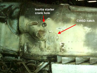 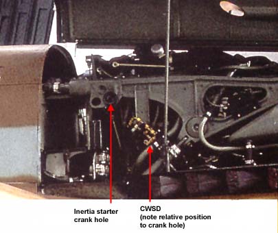 |
The CWSD allowed one to add a quantity of fuel to the oil in order to thin the oil and allow it to circulate more quickly; in cold climates, oil has a tendency to congeal (which is one reason today's lubricants feature additives such as viscosity improvers to allow freer flow at low and high temperatures). On the DB605D, this device had to be relocated higher due to the introduction of an improved oil de-aeration system, and this provides us with the second and most definitive identifier of a D-model engine. The device was now almost perfectly parallel with the inertia starter crank hole.
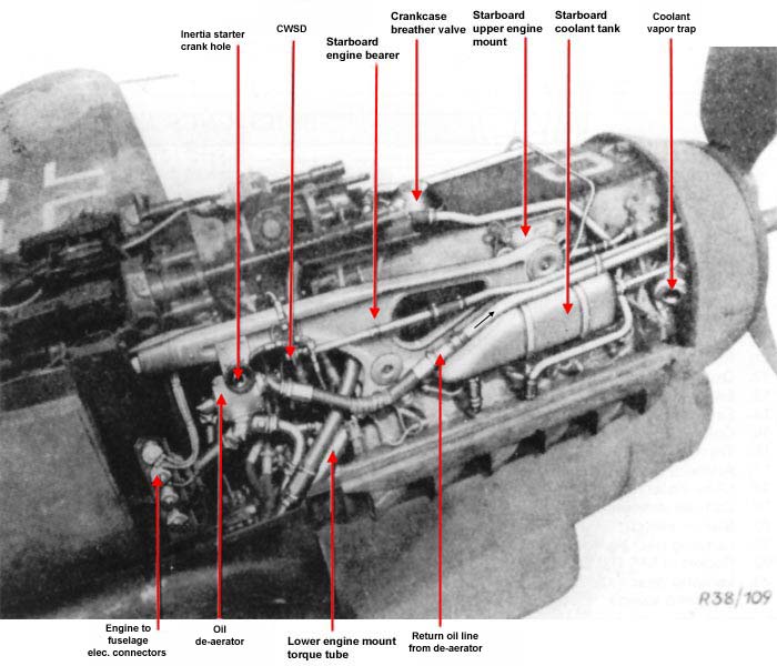 |
In the notated factory photograph at left, the CWSD circuit and other associated identifiers of DB605D-engined aircraft are indicated. |
| In the shots at left (furnished again by Mr. D'Amico), we can see examples of this higher mounted hatch clearly marked with a yellow circle to indicate access to a fuel system component: | 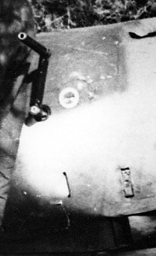
 |
| There is also one further handy "quick identifier" point for a DB605D-engined aircraft that is clearly visible when the starboard cowling is open, and this is a row of four electrical connectors mounted vertically against the firewall. These are electrical connectors between the engine and the fuselage, and are clearly visible in this shot of G-10 W.Nr. 610937 under restoration. | 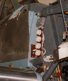 |
So, when examining photographs of a late G or K aircraft, there is a fairly reliable indicator on either side of the aircraft which will help establish the possibility of the aircraft being an AS or D engined variant.
The next installment will be an overview of cowling development from the G-2 through the K-4.